Risk assessment in mechanical engineering

CE marking was introduced by the EU with the aim of reducing technical barriers to trade. In the context of CE marking, this goal is achieved by a harmonization concept of the European Commission, based on the so-called “New Approach”.

CE marking is intended to ensure that only safe products find their way onto the European market. Before affixing the CE marking, the manufacturer must carry out a conformity assessment to ensure that the respective product meets the requirements of the relevant EU directives/regulations. To do this, he must determine the applicable EU directives/regulations and then assess the conformity of his products with these requirements according to the specifications in the directives/regulations.

The basic health and safety requirements contained in the applicable directives are binding for the manufacturer. However, it is possible that the goals set with them cannot be achieved due to the state of the art. In this case, the machine must be designed and constructed as far as possible with these objectives in mind.

The Machinery Directive 2006/42/EC naturally has special significance for machine and plant construction. The Machinery Directive requires that a risk assessment be carried out by the manufacturer of the machine as part of the CE marking.

The risk assessment is required in order to identify the risks posed by products and, with the aid of risk analysis and risk assessment, to reduce the dangers – and thus provides the manufacturer with legal certainty if used correctly.

MRL, Annex I, 1st edition: The manufacturer of a machine or his authorised representative must ensure that a risk assessment is carried out to determine the health and safety requirements applicable to the machine. The machine must then be designed and constructed taking into account the results of the risk assessment.

In addition to the Machinery Directive, other EU directives and EU regulations also require the preparation of a risk analysis and assessment. Here is an exemplary list:

  • Machinery Directive 2006/42/EC
  • Low Voltage Directive 2014/35/EU
  • EMC Directive 2014/30/EU
  • Radio Equipment Directive 2014/53/EU
  • Pressure Equipment Directive 2014/68/EU
  • ATEX Directive 2014/34/EU
  • Medical Device Directive 93/42/EEC or Medical Device Directive (EU) 2017/745

Risk assessment

When a company builds, retrofits or interlinks machines, a systematically structured risk assessment is the most important basis for the safe execution of the product. The risk assessment according to EN ISO 12100 (formerly known as hazard analysis) is therefore the central design element for the development of safe machines according to the Machinery Directive.

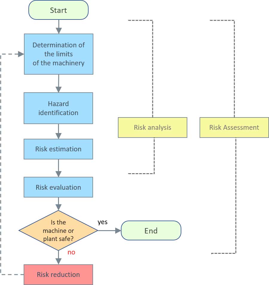
Risk assessment and risk reduction as an iterative process

The risk assessment according to EN ISO 12100 essentially follows these 5 steps:


  1. Darstellung iterativer Prozesses zur RisikominderungDetermining the limits of the machine
    This is where the basic conditions for the use of the machine are defined. What it is used for and by whom, in which context and under which boundary conditions (e.g. climatic, local, temporal)
  2. Risk analysis
    Identification of hazards for all life phases and tasks/operation modes
  3. Risk assessment
    based on the extent of damage and probability of occurrence
  4. Risk evaluation
    the decision whether risk reduction is necessary or not
  5. Risk reduction
    Find solutions to reduce or eliminate the risk

These 5-steps have to be passed through iteratively, since the application of protective measures can potentially create additional hazards or increase other risks. Thus, it is necessary to continuously check whether new hazards have arisen.

Risk analysis

DETERMINATION OF THE LIMITS OF THE MACHINE OR PLANT

When determining the limits of the machine, the aim is to define the framework conditions that apply to the use of the machine and thus to the considerations in the risk assessment. This includes determining the scope of application and the characteristics of the machine: e.g. area of application, space requirements, types of energy, auxiliary and operating materials, waste products, service life.

EN ISO 12100 divides the determination of the limits for this purpose into

  • Use limits
  • Space limits
  • Time limits
  • Other limits

The limits of use refer to the intended use of the machine and reasonably foreseeable misuse. The purpose of a shredder is to shred material. However, it can only do this within certain limits. For example, it may only be intended to process certain categories of waste or certain materials. The area of application could, for example, be designed exclusively for commercial use. Users may need to have certain qualifications or specific physical skills. (see EN ISO 12100 chapter 5.3.2)

The reasonably foreseeable misuse is not so much about looking into the crystal ball and predicting the future, but rather about collecting existing information and including it in the observation. For example, information from accident statistics or from customer service can be used to detect misuse such as

  • Use of materials not specified in the operating instructions
  • Non-compliance with the permissible parameters for processing the respective material
  • Maintenance work on an unsecured machine
  • Non-compliance with the operating instructions
  • Placing objects on the work surface
  • Machining of too large or too heavy materials
  • and so on

Aspects to be taken into account within space limits are the space required by machine and persons, interfaces between man and machine and interfaces between machine and energy supply. (see EN ISO 12100 Chapter 5.3.4)

The time limits refer to aspects of the service life of the machine and its components (tools, wear parts, safety components). How long should it be able to function safely? What maintenance intervals are recommended. What is the service life of tools, wearing parts, safety components, etc.? (see EN ISO 12100 Chapter 5.3.4)

Other limits include aspects such as the properties of the material to be processed, the required degree of cleanliness and environmental factors such as minimum and maximum temperature, indoor or outdoor operation, direct sunlight, dust and moisture tolerance, etc. (see EN ISO 12100 chapter 5.3.2)

HAZARD IDENTIFICATION

The hazard identification is the second step of the risk assessment. A hazard is the encounter of a person with at least one possible source of damage. The risk can then be derived from the hazards, in which the probability of occurrence of damage and the extent of damage are evaluated. The risk is thus the effect of a potential hazard.

The identification of hazards is the most important step in any risk assessment. This involves identifying and precisely describing all hazards emanating from the machine. After all, a risk can only be assessed if the hazard situation and the hazard event are clearly defined.

When identifying hazards, all phases of life and the tasks associated with these phases should be taken into account. So what we do is to mentally run through the logic of the machine (what it does, what are the processes, what does man do at the machine, …).

There are two main approaches to this:

  1. All phases of life and the associated tasks are run through to identify the hazards on the basis of the process sequences.
  2. All hazard zones are (mentally) gone through and the identified hazards are recorded. Again, this can also be done in a task-related manner.

While the second method is more of a static approach, and the dynamic aspects of the processes tend to fade into the background, it helps to focus attention on certain areas. It is therefore advisable to test both methods to see how they work, how you cope with them and what the result is – does it teach you anything new? 

What are phases of life?

Transport, installation, initial commissioning, operation, troubleshooting during operation, maintenance and finally decommissioning, dismantling, scrapping.

What are tasks?

A task can be an automatic process, the activity of one person or a combination of both.

Suppose we have a press that works in semi-automatic mode with manual loading. The machine is switched on and everything is ready for operation, the work pieces are waiting. A worker now loads them by hand, so this is an activity of one person within the life phase “operation” for the operating mode “semi-automatic”.
After insertion, the press stroke is triggered (foot switch, two-hand control, button, recognition of the part, …) – the stroke is triggered and an automatic process is executed. Then a person removes the part, which is an activity.

Task-based risk analysis

In the task-related risk analysis, the steps of a process and the hazards that arise in the process are considered. For example, the system checks what happens when the part is inserted, that is, what hazards arise. The advantage of this method is that it attempts to illuminate all risk situations of a process simultaneously. With this method it is possible to find a solution that eliminates all these hazards instead of going through individual hazards of a hazard list, most of which could have been found long ago. Solutions that have already been found should not be repeated many times in the risk assessment or operating instructions.

However, hazard lists are an important tool in this context. In Table B3, EN ISO 12100 has assigned a list of life phases and tasks that are typical for these life phases to one another.

Analysis in the team

It is advisable to carry out the risk analysis in a team in order to get a comprehensive picture and cover as many aspects as possible. The appointment of a moderator can help to ensure that solutions are not sought prematurely and that significant hazards are not overlooked.

RISK ESTIMATION

In the next step, a risk estimation must be carried out for the identified hazardous situations. The risk associated with a hazardous situation is a function of the extent of damage (severity of injury) and the probability of occurrence of the damage.

The risk is thus determined by the severity of the injury (minor injuries, serious injuries, death), the frequency and duration with which a person is present in the hazard area, human factors (experience, stress situation, etc.) and recognizability of the hazard, as well as enough time and opportunities to avoid it.

The individual factors are described in great detail in Chapter 5.5 of EN ISO 12100. However, EN ISO 12100 itself does not contain a system for quantifying the estimates. In “ISO/TR 14121-2 – Risk assessment – Part 2: Practical guide and examples of procedures”, however, some examples are given.

Risk Assessment - Risk Graph EN ISO 13849-1
Risikobeurteilung Risikograph EN ISO 13849-1

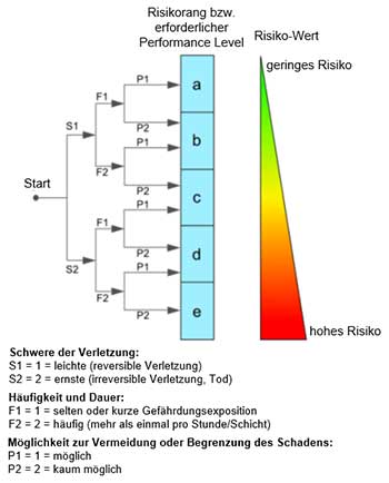
The risk graph is a proven method of assessing a hazard or risk, regardless of the type of machine. It can be used to find suitable measures for maintaining safety.

In practice, it is often the case that risk estimation in particular is one of the most difficult tasks for the persons involved. The risk is often a matter of personal estimation and cannot be calculated exactly, therefore one should not be so strict and want to work with accurate figures, even if this may be difficult especially for a design engineer. It is in the nature of things that two people who make an estimation about a risk often come to different results.

Accident statistics or information on accident situations can be helpful in risk estimation, for example, as provided by institutions such as AUVA, BAuA, VDW (Association of Machine Tool Manufacturers). However, some manufacturers now have their own statistics because they have started to collect, standardize and evaluate accident reports – this is particularly recommended for manufacturers of series.

Risk assessment

Following the risk estimation, the risk assessment is carried out to determine whether risk reduction is necessary for the identified hazards. If necessary, appropriate protective measures are to be selected and applied. Otherwise, the risk can be considered sufficiently reduced and the next hazard can be identified.

RISK REDUCTION

Risk reduction is carried out according to the “three-step procedure”, which EN ISO 12100 describes in detail in Chapter 6. This stipulates that in the first step, constructive measures for risk reduction must be taken, which can reduce or avoid a potential hazardous situation from the outset.

Step 1: Inherently safe design

An example of an inherently safe design would be a scissor lift whose mechanism is operated by a threaded screw. Although this is slow, a sudden failure of the lifting mechanism is impossible with this construction method – in contrast to cable-operated solutions or pneumatic or hydraulic systems.

If no further reduction or elimination of hazards can be achieved by the selection of design features, the shielding of potential sources of danger by means of separating or non-separating guards or complementary protective measures must be applied.

Step 2: Safeguarding and complementary protective measures

Using the example of the scissor lift, the failure of the lifting mechanism was constructively excluded. However, there are numerous danger points along the lifting mechanism where fingers can get trapped, for example. Here fenders can prevent intervention.

In the third and last step of the three-step procedure, risk reduction measures can be provided in the information for use.

Step3: Information for use

This information for use can be realised by affixing warning signs, but also by safety instructions pictograms, labels, warning devices such as optical or acoustic signals or information in the operating instructions.

The information for use must contain all the information necessary for the safe and correct use of the machinery. In this respect, it must also inform and warn the user of the residual risk remaining after all risk reduction measures have been taken. In other words, the user must be informed of any hazards that may arise when using the machine.

After each of the three steps,

  • Inherently safe design,
  • Safeguarding,
  • Information for use

it must be determined whether the risk reduction is appropriate. The comparison of the risks shows whether the objectives have been achieved and the risk has been sufficiently reduced.

If additional hazards have been created, these must be added to the list of hazards.

All identified hazards must be processed according to this procedure model.

DOCUMENTATION OF RISK ASSESSMENT AND RISK REDUCTION

The documentation shall set out the procedure used and the results obtained. Information is given in Chapter 7 of EN ISO 12100.

Other blog posts